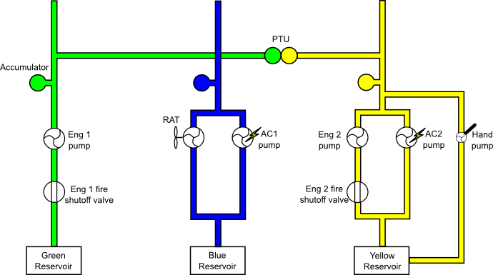
There are three continuously operating hydraulic systems, designated green, yellow and blue.
Each hydraulic system has its own reservoir. The reservoirs are pressurized by bleed air to prevent cavitation. The normal source is engine 1, but if pressure becomes low bleed air is taken from the cross-bleed duct. The reservoirs are monitored for low fluid level, low air pressure and overheat.
The green and yellow systems are normally pressurized by engine driven hydraulic pumps. These pumps have a upstream shutoff valve that cuts off the flow of hydraulic fluid when the associated engine fire button is pushed. The yellow hydraulic system may also be pressurized by an electric pump. This pump may be powered by either AC2 or external power. It operates automatically to partially pressurize the yellow system when the cargo doors are moved. It may be selected on manually using a switch on the hydraulics panel, in which case it fully pressurizes the yellow system. Operation is signified on the ECAM HYD page by the hollow white triangle next to the word ELEC becoming solid green. A hand pump is provided to partially pressurize the yellow system and enable the cargo doors to be opened in the absence of electrical power.
The blue system is normally pressurized by an electric pump powered by AC1. This pump operates whenever AC power is available unless the aircraft is on the ground with both engines shut down. In this case it may be operated using the BLUE PUMP OVRD pushbutton on the maintenance panel.
In an emergency situation, the blue system may also be pressurized by a Ram Air Turbine (RAT). The RAT deploys automatically if both AC BUS 1 and AC BUS 2 are lost. It may also be deployed manually using the RAT MAN ON button on the hydraulics panel. The RAT cannot be restowed in flight. Deployment of the RAT is indicated on the ECAM HYD page by the hollow white triangle next to the word RAT turning solid green.
The engine driven pumps and the electric pumps supply 3000psi. The RAT supplies 2500psi. The pumps are all monitored for low output pressure. The electric pumps are also monitored for overheat.
A Power Transfer Unit (PTU) allows cross pressurization between yellow and green systems without transfer of fluid. It activates automatically when differential pressure between the two systems is greater than 500psi. The PTU is inhibited during the first engine start and self tests during the second engine start sequence. The PTU is also inhibited during, and for 40 seconds after, automatic operation of the yellow electric pump. Operation of the PTU is indicated by a HYD PTU memo appearing on the E/WD.
An accumulator is provided for each system to help maintain constant pressure during transient demands. Each system also has a priority valve to cut off heavy users (flaps, slats, gear, emergency generator) if system pressure gets too low to operate the flight controls.
Each system has a leak measurement valve upstream of the primary flight controls. These can be closed by operation of switches on the maintenance panel. The effect of closing these valves is to shut off hydraulic supply to the primary flight controls.
The flight controls all receive hydraulic power from at least two sources. This is detailed in {TODO: add flight controls xref here once its done}. The other hydraulic systems are powered as follows:
| Green | Yellow | Blue |
|---|---|---|
|
|
|