The air conditioning system is controlled by two dual lane air conditioning system controllers. They provide inputs to the pack flow control valves, the packs, the hot air pressure regulating valve (controller 1), the cockpit trim air valve (controller 1) and the cabin trim air valve (controller 2). There is no effect from a single lane failure, as the backup lane takes over all duties.
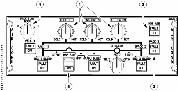
The pack flow control valves regulate flow of warm pre-conditioned air (originating from the pneumatic system) to the packs. They are pneumatically operated, electrically controlled and spring loaded to the closed position. They automatically close when a pack overheats, during starting or when either the fire or ditching push buttons are pressed. They can also be manually closed by pushing the related PACK button (Figure 1, “Air conditioning controls” (3)). The amber light in this button indicates valve position disagreement or pack overheat (monitored at compressor outlet and pack outlet).
The PACK FLOW selector (Figure 1, “Air conditioning controls” (4)) allows the selection of flow rate from 80% to 120%. If only one pack is in use or the APU is supplying bleed air, the system will deliver high flow regardless of this selection.
Each pack consists of an air cycle machine and a ram air duct for the heat exchangers. The air cycle machine turbine also drives a cooling fan that draws cool air over the heat exchangers. Temperature in the pack is regulated by bypassing air around the air cycle machine via a turbine by-pass valve and by modulating the ram air intake flaps. These flaps are closed during take-off (take-off power set, main gear struts compressed) and landing (main gear struts compressed, speed above 70kt until speed less than 70kt for 20 seconds) to avoid FOD ingestion. In the event of failure of the air cycle machine the pack may still be operated with reduced flow using the heat exchanger only.
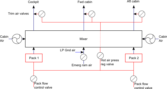
The cooled air from the packs is then fed into a mixer unit where it is mixed with recirculated air from the cabin. The mixer then supplies air to three independent zones, the cockpit, the forward cabin and the aft cabin.
Temperature requirements of between 18°C and 30°C are set on the air conditioning panel (Figure 1, “Air conditioning controls” (1)), and cabin zones may be trimmed ±2.5°C by controls on the forward attendants panel. The output temperature for each zone is a function of actual temperature (measured by sensors in the cockpit and in the lavatory extraction circuit and galley ventilation systems) and demanded temperature. Controller 1 regulates cockpit temperature and controller 2 regulates cabin temperature. The packs are controlled to provide air at the lowest temperature required, then the temperature of the other zones is trimmed by mixing in hot air that has bypassed the packs via the hot air pressure regulating valve and trim air valves. If temperature requirements cannot be met the system will attempt to increase flow. If LO flow is selected, the system will override to NORM flow. The system can also increase flow by increasing bleed pressure by requesting increases in engine minimum idle or APU flow output as required.
The hot air pressure regulating valve is pneumatically operated, electrically controlled and spring loaded to the closed position. It closes automatically in the case of a duct overheat (which also closes the trim valves), if either the cockpit trim valve fails or both cabin trim valves fail, or if both lanes of a system controller fail. It can be closed manually with the HOT AIR button (Figure 1, “Air conditioning controls” (2)). If the hot air pressure regulating valve fails open, there is no effect as the trim valves take over its duties. If it fails closed, optimized regulation is lost and the packs are used for all regulation (pack 2 controls to the mean of FWD and AFT temperatures). The amber FAULT light in the HOT AIR button indicates duct temperatures in excess of 88°C. It will extinguish once temperature drops below 70°C and OFF is selected.
Control of zone temperature is provided by a Zone Control Computer. This computer controls the trim valves and provides data to the pack controllers. It is dual channel. Failure of a single channel gives a ALTN MODE indication on the ECAM COND page. If a dual channel failure occurs, there is no trimming and zone temperature is purely a function of pack outlet temperature. A dual channel failure produces a PACK REG legend on the ECAM COND page, with amber crosses shown for the trim system and zone temperatures.
The mixer may also be supplied with ram air. This is controlled with the RAM AIR push button (Figure 1, “Air conditioning controls” (5)) and is used in the case of double pack failure or smoke removal. A check valve located in the ram air duct opens only when cabin differential is less than 1 psi, thus preventing backflow if the cabin is pressurised. The RAM AIR push button also opens the outflow valve to approx. 50% if the outflow valve is under automatic control and differential pressure is less than 1 psi. Since operation of the ram air valve leads to aircraft depressurisation, it should not normaly be operated above FL100/MORA. Opening of the ram air duct is inhibited if the DITCHING button has been pressed. When parked, low pressure conditioned air may be fed into the ram air duct to allow ground conditioning. The packs must be turned off when LP ground air is used.
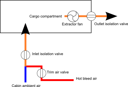
Cargo compartment air conditioning is fully automatic. Ambient cabin air enters the compartment via an inlet isolation valve. An extractor fan or differential pressure is used to exhaust the air overboard via an outlet isolation valve. Operation of the two valves and the extractor fan is controlled automatically by a cargo ventilation controller.
Cargo compartment heating is provided by hot bleed air that enters via a trim air valve. This valve is controlled by a cargo heating controller. The bleed air source for trimming the forward hold is the same duct that is used for trimming the cockpit and cabin and thus uses the same hot air valve. The rear compartment has its own independent hot air valve.
The cargo heat panel is on the right hand side of the overhead panel. Two rotary selectors set temperature in the compartments, with the normal 12 o'clock position being approx. 16°C.