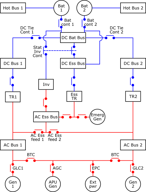
The electrical system consists of a three phase 115/200V 400Hz AC system and a 28V DC system.
Primary AC supply is from two 90 KVA engine driven integrated drive generators (IDGs). Each IDG has an associated generator control unit (GCU) which provides frequency, voltage and generator line contactor (GLC) control. A third 90 KVA generator is driven by the APU. This generator, along with ground power, is controlled by the Ground and Auxiliary Power Control Unit (GAPCU). Each of the three main generators is capable of supplying the power requirements of the entire system. The generators cannot be connected in parallel, and are automatically brought on line according to priority rules. The IDGs are highest priority, followed by EXT PWR when connected, followed by the APU generator.
A 5KVA hydraulically powered (blue system) constant speed emergency AC generator and associated GCU provide power in the event of failure of normal sources. In addition a 1KVA static inverter supplies emergency power to part of the AC essential bus if the batteries are the only remaining power source.
Primary DC power is provided by two 200A transformer rectifier units with automatic protection circuits that disconnect the TR in the event of overheat or minimum current. A third identical TR, the "essential" TR provides power for the DC Essential bus in the event of loss of all normal AC generators (the Ess Tr is capable of drawing power from the emergency AC generator) or in the event of loss of one or both of the main TRs.
Two 23Ah batteries are also provided for emergency DC power. Each has an associated battery charger limiter (BCL) to monitor charging and control its battery contactor. The minimum required offline battery voltage is 25.5V. If the battery voltage is below minimum, they can be recharged by connecting the batteries to the battery bus and applying external power for approximately 20 minutes. In the event of failure of all other power sources, the batteries can provide emergency power for approximately 30 minutes.
Two types of CB are fitted. Monitored CBs are green and trigger ECAM warning messages when out for more than one minute. Non-monitored CBs are black and do not cause ECAM warnings. The Wing Tip Brakes (WTB) CBs have red caps to prevent them being reset.
In normal flight, the AC Busses are supplied via a their associated generator and the AC Ess Bus is supplied from AC Bus 1 (i.e. AC Ess feed 2 is open). TR1 supplies DC Bus 1, the battery bus and the DC essential bus, and TR2 supplies DC Bus 2 (i.e. DC Tie Cont 2 is open). When battery charging is required the BCL closes the required battery contactor to connect the battery to the DC Bat Bus.
If a single engine driven generator is lost, the system will automatically replace it with the APU generator if available, or else it will shed part of the galley load and route power from the other engine driven generator. If all main generators are lost, AC Bus 1 and AC Bus 2 are lost. If aircraft speed is sufficiently high (> 100kt) a ram air turbine (RAT) automatically deploys. This powers the blue hydraulic system which, in turn, powers the emergency AC generator. Once this generator is online (approx 8 seconds for RAT deployment and generator coupling), it powers the AC Ess bus, the Ess TR and hence the DC Ess bus. If the RAT stalls or the aircraft speed is below 100kt, the AC Shed ESS and DC shed ESS buses are shed and the remains of the essential system are powered via the batteries and static inverter. Once on the ground, the DC bus is automatically connected to the batteries below 100kt and the AC Ess Bus is shed below 50kt.
A "smoke configuration" is provided that sheds 75% of electrical equipment, the remaining 25% being controlled by easily accessible CBs on the overhead panel (with the exception of equipment attached to the hot busses). It is essentially the same as for the loss of all main generators, except the fuel pumps are connected upstream of the Gen 1 line connector.
If AC bus 1 fails, power for the AC Ess bus must be re-routed from AC bus 2. Automatic re-routing is available on some aircraft. Manual re-routing is achieved by pressing the AC Ess feed pushbutton. TR1 is lost causing the Ess TR to supply the DC Ess bus and, after a 5 second delay, DC bus 2 to provide power to DC bus 1.
If both main TRs are lost, DC Bus 1, DC Bus 2 and the DC Bat bus are lost. The DC Ess bus is powered by the Ess TR.
With the engines shut down on the ground, either the APU or external power may be used to supply the entire system. In addition, external power can supply the AC and DC GND/FLT buses directly without supplying the entire system using the MAINT BUS switch in the forward entrance area.
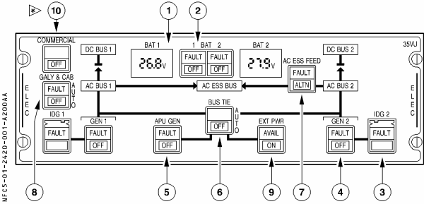
When an IDG must be disengaged, the IDG button should be pressed and held until the Gen FAULT light comes on, but should not be held for more than 3 seconds.
In the event of a generator having out of limit load but continuing to power its AC bus, the amber FAULT light in the GEN button will not illuminate.
Pressing the BUS TIE button (OFF position) manually opens the bus tie contactors (BTCs). In this case, only IDG 1 can supply AC 1 and only IDG 2 can supply AC 2. This may be used to isolate a short circuit that has affected both halves.