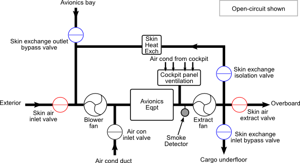
Ventilation of the avionics is primarily provided by two fans, one acting as a blower, the other as an extractor. Control is provided by the Avionics Equipment Ventilation Computer (AEVC). The system's normal modes are:
- Close-circuit
Used when skin temperature is low. The skin exchange outlet bypass, inlet bypass and isolation valves (shown in blue in Figure 5, “Simplified avionics cooling schematic”) are open and all other valves are closed. This leads to air being drawn from the avionics bay and exhausted into the underfloor of the cargo bay, with a return loop via the skin heat exchanger.
- Intermediate
Used in flight when skin temperature is high. This is similar to close-circuit except the skin air extract valve is partially opened to allow some air to exhaust overboard.
- Open-circuit
Used for ground operations (oleo compressed, thrust below TO) with a high skin temperature. In this mode only the skin air inlet and extract valves (shown in red in Figure 5, “Simplified avionics cooling schematic”) are open, meaning air from outside the aircraft is moved across the avionics equipment and then exhausted externally.
The skin temperature thresholds are different for flight and ground cases and incorporate a dead band to prevent rapid mode switching. The bands are 9°C to 12°C on the ground and 32°C to 35°C in flight.
Cooling of the cockpit panels is provided by drawing air conditioned air from the cockpit over the panels in all modes.
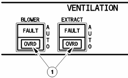
If a fault occurs with one of the fans, a FAULT light will illuminate on the associated button (Figure 6, “Avionics ventilation controls” (1)). The BLOWER FAULT light is also used to indicate a duct overheat. Selecting OVRD puts the system in closed-circuit configuration and opens the air conditioning inlet valve so that air conditioned air assists with the cooling. If the BLOWER button is in OVRD, the blower fan is stopped. If the EXTRACT button is in OVRD, the extract fan is controlled directly from the pushbutton and both fans continue to run. {TODO: There appears to be a conflict between the text and the diagram with regards to the action of the skin exchange inlet bypass valve when EXTRACT is in OVRD. The diagram essentially indicates air con as sole intake and no exhaust!}
A smoke detector is situated immediately upstream of the extract fan. If smoke is detected both FAULT lights come on. Selecting OVRD on both buttons puts the system in smoke removal mode. This is similar to open-circuit except the intake air is provided by the air-conditioning rather than from outside the aircraft and the blower fan is stopped.
{TODO: Controller failure - manual is very unclear what happens here.}