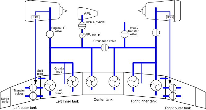
Each wing incorporates an inner tank, an outer tank and a vent surge tank. A center tank is incorporated into the fuselage.
The outer tanks are used for wing bending and flutter relief. There are two electrical transfer valves connecting each outer tank to its associated inner tank. These are controlled by level sensors in the inner tanks. Each inner tank has two sensors, and each of these sensors controls a symmetrical pair of transfer valves. When any sensor detects the fuel level in an inner tank falling below approximately 750kg, it opens its symmetrical pair of transfer valves (i.e. one for each wing), allowing all outer tank fuel to transfer simultaneously to the inner tanks. This event is indicated by the E/WD memo "OUTER TK FUEL XFRD" and green triangles appearing in the outer tanks on the ECAM FUEL page. The transfer valves, once open, remain open until the next refueling operation.
The outer tanks are also connected to the inner tanks by a spill pipe. This allows fuel returned to the outer tanks by the fuel recirculation system (see below) to flow to the inner tanks if the outer tanks are already full. It is also used during refueling, since fuel destined for the inner tanks is routed via the outer tanks.
The vent surge tanks protect against thermal expansion of fuel. Fuel may expand by at least 2% (equivalent to ∆20°C) without spilling. There are no cockpit indications for these tanks.
The inner, outer and vent tanks each have overpressure protectors. The center tank has an overpressure protector connected to the left inner tank.
There are six electrical fuel pumps, two in the center tank and two in each inner tank. Under normal conditions the fuel system is split, with one center tank pump and the two same side wing tank pumps supplying each engine. A double motor cross feed valve, controlled by the X FEED button, allows the fuel system to be unified. A green OPEN light in this button indicates that the valve is in the fully open position.
The inner tanks incorporate suction valves that allow for gravity feeding of fuel in the event of loss of both pumps. The service ceiling of the aircraft may be affected if the fuel has not had time and altitude to deaerate. Gravity feeding is not available from the center tank.
The wing tank pumps operate continuously unless switched off with their associated TK PUMPS button. The #1 pump in each tank is powered by AC1 and controlled by DC1, and the #2 pump is powered by AC2 and controlled by DC2. The #1 pump in each tank also has an alternate power feed directly from its associated IDG, and an alternate control feed from DC ESS. The pumps incorporate pressure relief sequence valves in order that fuel is delivered preferentially from the center tank if the associated center tank pump is producing normal output pressure. An amber FAULT on their associated button indicates low delivery pressure with the button in the "On" position.
The center tank pumps have automatic and manual modes, controlled by a single MODE SEL button. The FAULT light in this button indicates that fuel is being burnt out of sequence, inferred from >250kg in the center tank with <5000kg in one of the wing tanks. In general, when in automatic mode a pump is inhibited whenever slats are extended, whenever its associated wing tank is full (with a latch until 500kg has been burnt from the tank) or once 5 minutes have elapsed since the center tank reached low fuel level. The exception is that for two minutes after its associated engine has been started, the pump is only inhibited by the center tank low fuel condition. This allows the center tank fuel lines to be pressurized if center tank fuel is going to be used. In manual mode, all "auto stop" logic is inhibited and the crew must provide the logic directly using the CTR TK PUMP buttons. The FAULT light in each of these buttons indicates low delivery pressure with the associated pump operating. The #1 pump is powered by AC1 and controlled by DC1, and the #2 pump is powered by AC2 and controlled by DC2. Note that takeoff with the center tank pumps operating is prohibited.
On the ECAM FUEL page, if a fuel pump is shown as an amber boxed LO, the pump is on but it is not producing adequate pressure. An amber box with a cross line indicates that a pump has been switched off manually.
Fuel pressure for APU startup is normally provided by the left hand side of the fuel system. If pressure is unavailable due to loss of tank pumps or loss of normal AC supply, an APU fuel pump can be used. This is normally powered by the AC ESS SHED BUS, but has an alternate feed directly from the AC STAT INV BUS.
The design of the engine fuel system (see Section 19.4, “Engine fuel system”) and the requirement for IDG cooling leads to some fuel being returned to the tanks. This is routed to the outer tanks and from there to the inner tanks via the spill pipe or transfer valves depending on the configuration of the fuel system. Overfilling is prevented by controlling the center tank pumps. Overfilling (and hence venting) is possible with the center tank pumps in manual mode.
The refuel coupling is situated under the wing outboard of the #2 engine, near the leading edge. The refuel panel is situated on the fuselage below the right wing. Fueling is usually automatic, controlled by setting the required quantity with the preselector rocker switch and selecting the MODE SELECT switch to REFUEL. Manual control is available by selecting the REFUEL VALVES switches to OPEN and SHUT as required. Fueling with battery power is available by momentarily selecting the BATT POWER switch to ON. Gravity fueling is also possible. The REFUELG memo on the E/WD only indicates that the refuel panel door is open.
A de-fuel/ transfer valve connects the right hand side of the fuel system to the refueling/ de-fueling gallery. It is opened by selecting the MODE SELECT switch to DEFUEL. An amber light illuminates next to the switch to indicate that the valve is open.
A Fuel Quantity Indication (FQI) system provides fuel mass, quantity and temperature data to the ECAM and controls automatic refueling. This system comprises an FQI computer, a set of capacitance probes to measure fuel level and temperature, a densitometer and a Capacitance Index Compensator (CIC) (used in case of densitometer failure).
Degradation of a fuel quantity sensor is indicated by two amber dashes across the last two digits of the FOB value. On the ECAM FUEL page, the affected tank also shows the dashes on its quantity value.
Fuel temperature exceeding a limitation results in a master caution and the fuel temperature of the affected tank being shown in amber on the ECAM FUEL page.
A shroud drain mast is situated under the fuselage. This drains any fuel that leaks from the system.
Each tank has a magnetic fuel level indicator to allow fuel to be measured manually. These should normally be flush with the aircraft surface. Each tank also has a water drain valve. These should be checked for leaks.