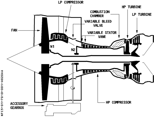
The engines are designated CFM56-5B. Each engine has two rotors. The low speed N1 rotor consists of a front fan, a four stage compressor and a four stage turbine. The high speed N2 rotor consists of a nine stage compressor and a single stage turbine. The N2 rotor also drives an accessory gearbox located at the bottom of the fan case. The combustion chamber has 20 fuel nozzles and two igniters.
Each engine is controlled by a two channel Full Authority Digital Engine Control System (FADEC), also known as the Engine Control Unit (ECU). One channel is active, the other is a standby with automatic failover. The active channel toggles after each flight {TODO: this is an assumption - check it}.
The FADECS are self powered by an internal magnetic alternator when N2>58%. Channel A may also be powered by DC ESS. Channel B may also be powered by BAT BUS for engine 1 and DC BUS 2 for engine 2. Pushing the FIRE button for an engine disconnects the FADECs from their external power sources. After power is first applied to the aircraft the FADECs power up for 5 minutes to allow self testing {TODO: again an assumption - to check}, then power down until IGN/START is selected on the ENG MODE switch. They continue to be powered for 5 minutes after their respective engine master switch is turned off.
Data for the FADECs is directly sourced from the ADIRS, engine sensors and thrust levers. All other required data is amalgamated and supplied by an Engine Interface Unit (EIU).
The primary function of the FADECs is responding to thrust demands from the thrust levers or autothrust system whilst respecting thrust rating, idle settings and N1 and N2 limitations. This is acheived by controlling flow of fuel both to the engine and back through the recirculation system to the tanks. Engine performance is further optimised through control of variable bleed valves, variable stator vanes and turbine and rotor clearances.
During a start sequence, the FADEC also controls the start valve, HP fuel valve and ignition. For automatic starts N1, N2, fuel flow and EGT are actively monitored, and automated abort and recycle is provided. Passive monitoring of these parameters is provided for manual starts.
When reverse thrust is selected, the FADECs control the blocker doors.
The thrust levers can only be moved manually. There are 2 detents and 3 stops on the thrust quadrant. These are the TOGA stop, MCT/FLX detent, CL detent, Idle stop and Max reverse stop. In addition there is a notional (i.e. non-phyiscal) reverse idle detent acheived by pulling up the reverse levers and selecting a position slightly behind the idle stop.
In normal operation, autothrust is available when the thrust levers are in the range between the idle stop and CLB detent. When an engine out condition is detected, autothrust is available between the idle stop and MCT/FLX detent. When the autothrust is not engaged, either because it is not armed or because the thrust lever is set outside the autothrust range, the Thrust Lever Angle (TLA) maps directly to an N1 demand. Each of the detents/stops maps to its given limit, and there is a straight line TLA to N1 relationship between these positions.
The N1 for the MCT/FLX detent will be MCT except when on the ground with a FLEX temperature set, in which case it will be the computed FLEX N1. Once airborne the detent reverts to MCT when the thrust levers are either moved to the TOGA stop or moved to or through the CL detent.
The N1 for the idle detent is normally "modulated idle", a value regulated according to bleed system demand. When in flight with the flap lever not at zero position, the idle detent is "approach idle". This is an idle setting designed to allow rapid acceleration to TOGA thrust and it is regulated according to aircraft altitude without regard to bleed configuration. The N1 for the notional reverse idle detent is "reverse idle", a value slightly higher than forward idle thrust.
When the autothrust is engaged, the N1 it can command is limited to between the N1 for the TLA set and the N1 at the idle detent.
A special case is alpha floor protection. If a very high angle of attack is detected, TOGA thrust is set regardless of TLA. See {TODO: cross reference once done}.

The engine fuel system is pressurised by two engine driven pumps {TODO: engine driven is inferred from the diagram in 1.70.40.1000- check its true}, a low pressure (LP) pump and a high pressure (HP) pump. These provide a supply of high pressure fuel to the inlet of a Fuel Metering Valve (FMV). The FADEC controls this valve to provide the fuel flow required to satisfy the N1 demand and keep all other engine parameters within their defined limits. A bypass valve located immediately before the FMV modulates to maintain a constant pressure drop across the FMV in order to maintain a linear relationship between FMV position and fuel flow acheived. This bypass valve is also used by an independent overspeed governor that limits N2 to 107.2% in the event of FADEC malfunction.
The FMV, along with other actuators under the control of the FADEC (variable stator veins, variable bleed valves etc) are operated hydro-mechanically using high pressure fuel tapped from the fuel lines after the HP pump.
Two shut off valves are incorporated into the fuel line, a low pressure shut off valve located before the LP pump, and a high pressure shut off valve located after the FMV. Both these valves are closed when the engine master switch is selected off, but only the low pressure shut off valve is closed by the fire button.
Fuel is also used to provide IDG cooling. The FADEC modulates the bypass valve and fuel return valve to control flow of fuel through the IDG oil cooler to acheive the required cooling.
The supply side of the engine oil system consists of an oil supply pump that draws oil from the oil tank and passes it through an oil filter to the bearings and gearbox. The oil filter incorporates a by-pass valve in case of clogging. Oil pressure and temperature are monitored downstream of the filter.
The scavenge side consists of four scavenge pumps {TODO: inferred from diagram 1.70.50}, through a scavenge filter then back to the oil tank via the servo fuel heater and fuel/oil heat exchanger. The scavenge filter incorporates a bypass valve in case of clogging.
Bleed air is tapped at the 5th and 9th stages of the HP compressor and from the fan. It is used to supply the pneumatic system (see Section 7, “Pneumatics”) and to provide cooling air to the active clearance control systems. The active control clearance systems are a function of the FADEC which uses fuel pressure to modulate bleed air control valves in order to control the temperature, and hence size, of the turbine casings and the HP compressor casing. The LP Turbine Clearance Control (LPTCC) system uses fan air to cool the LP turbine case. The Rotor Active Clearance Control (RACC) system uses 5th stage bleed air to cool the HP compressor case. The HP Turbine Clearance Control (HPTCC) system uses both 5th and 9th stage bleed air to cool the HP turbine case.
Reverse thrust is acheived using four pivoting blocker doors per engine which are used to deflect the airstream from the fan forward. Each blocker door has a hydraulic actuator, a latch and a position switch. The FADEC moves the doors using a Hydraulic Control Unit (HCU) consisting of a pressurizing solenoid valve and a directional solenoid valve. An independent hydraulic shut off valve controlled by the spoiler elevator computers (SECs) controls inlet pressure to the HCU.
Actuation required input from a number of systems. Firstly the SECs must receive a signal from the thrust levers to open the shut off valve and allow pressure to the HCU. Secondally, the EIU must receive a signal from the thrust levers to enable the directional solenoid valve, which will otherwise be inhibited. Finally, at least one channel of the FADEC must receive the correct signals from the thrust levers, N2 sensor and LGCIU (via the EIU). If it detects the TLA is in the reverse segment, N2>50% and both main gear compressed, the FADEC signals the HCU to open the blocker doors.
When on the ground with the engine running and N1<70%, an auto restow function is available. This stows any door that is detected unstowed with reverse thrust not selected.
Idle protection is available in all flight phases when reverse thrust is not selected. This selects idle thrust if pressure is detected in the HCU and any door is detected unstowed or with an indefinite position. It also selects idle thrust regardless of HCU pressure if all four blocker doors are detected unstowed.
The FADEC start module receives input from the engine master switches, the engine mode selector, the manual start buttons and the LGCIU, all via the EIU. It controls the start valve, the igniters and the HP fuel valve. The engine master switch also independenly inhibits the opening of the HP fuel valve when selected off.
Each engine has two identical independent igniter systems. Normally, each FADEC channel controls a single igniter system, but in failure cases both igniter systems can be controlled by a single FADEC channel.
For automatic starts on the ground, a single igniter is used. It is energised at 16% N2 and de-energised at 50% N2. The FADEC toggles between the four channel/igniter system permutations after each start.
For manual starts and in flight starts, both igniters are energised when the master switch is turned on. De-energisation at 50% remains automatic.
Automatic continuous ignition is provided if a flame out is detected. It is also provided if the EIU fails whilst the engine is running.{TODO: There is a third case: Engine running and ignition delay during start - this doesn't seem to make much sense} Continuous ignition can also be selected manually using the engine mode selector.
Engine spin up is provided by an air turbine starter that is powered by the pneumatic system. Supply of air to the turbine is controlled by a start valve which is controlled electrically by the FADEC. There is also a handle on the engine to allow the start valve to be operated manually if electrical control fails. In an automatic start sequence, if the starter is required (i.e. on the ground or insufficient windmilling speed), the FADEC opens the start valve at the start of the sequence and closes it at 50% N2. In a manual start sequence the FADEC still closes the start valve at 50% N2, but opening of the valve is acheived by pressing the manual start push-button. All manual start sequences are starter assisted.
For automatic starts, the FADEC opens the HP fuel valve at 22% N2 on the ground and 15% N2 in flight. For manual starts, the HP fuel valve opens when the engine master switch is turned on.
The FADEC also provides start monitoring. It will detect hot starts, hung starts, stalls and wet starts and provide an appropriate ECAM message. If these conditions are detected during an automatic start, the FADEC will automatically run an abort sequence including dry cranking and then attempt further starts. An automatic start can be aborted at any time by turning the engine master switch off. This closes both fuel valves and signals the FADEC to close the start valve and de-energise the ignition. Dry cranking, if required must then be done manually using the crank position of the engine mode selector and the manual start button. For manual starts, the FADEC has very limited authority to abort a start. The sole case is when on the ground and a start EGT exceedance occurs before 50% N2. In all other cases, it is the pilot's responsibility to interrupt the start sequence by either deselecting the manual start button or turning the engine master switch off as appropriate.
The completion of the start sequence is indicated by the grey background on the N2 indicator disappearing. The stable N2 value is approximately 58%. It is recommended that the engines are operated at or near idle for at least two minutes after start.
The warning lights below the engine master switches have two segments, a red FIRE segment and an amber FAULT segment. The FIRE segment aids the crew in selecting the correct master switch during an engine fire drill. The amber segment indicates an aborted automatic start or an HP fuel valve position disagreement.
The N1 gauges display a caution range by an amber line representing TOGA N1 and a warning range by a red arc. The lower end of the red arc represents max N1 (104%). If N1 enters the caution range, the N1 needle and digital indication, which are normally steady green, pulse amber. If N1 enters the warning range, they pulse red, and a red tell tale is left at the maximum acheived N1. A blue circle above the index indicates the N1 corresponding to the current TLA. If the autothrust is active, trend indications are displayed as green triangles next to the needle. The longer of the two triangles represents the difference between the demanded and actual N1. The smaller of the two triangles shows the direction and rate of current N1 changes. If the last digit of the digital display is a dash, it indicates that N1 data is degraded due to failure of both N1 sensors.
The status of the reverses is also indicated on the N1 gauge. An amber REV indicates that at least one door is unstowed or unlocked. In flight this indication will initially flash for 9 seconds. The REV becomes green when all the reverser doors are fully deployed.
The current thrust limit mode and N1 rating limit are displayed to the right of the N1 gauges. If a FLX takeoff is selected, the FLX temperature will also appear here.
The EGT, like the N1 gauge, has a caution range indicated by an amber line and a warning range indicated by a red arc. The bottom of the red arc is at max permissable EGT (950°C). If EGT exceeds this value, the needle and digital display pulse red, and a red tell tale is left behind at maximum acheived EGT. The amber line is the start limit (725°C) during the start sequence. Otherwise, except when operating at high power, it is 915°C. If actual EGT is above the amber line value, the needle and digital display pulse amber.
N2 is represented as a digital value only. This is normally green, but turns red with a red cross next to it if N2 exceeds 105%. If both N2 sensors fail the last digit is replaced by an amber dash. The numbers have a grey background during the start sequence. The removal of this grey background indicates completion of the sequence.
Fuel flow is also indicated as a digital value only.
An amber CHECK indication below the N1, N2, EGT or fuel flow values indicates a discrepancy between the values on the FADEC-DMC bus and those displayed. {TODO - how does this occur?}.
Fuel used, oil quantity, oil pressure, oil temperature, N1 vibration, N2 vibration and nacelle temperature are displayed on the ECAM Engine page. During the start sequence the nacelle temperature is replaced by indications of start valve position, available bleed pressure and ignitor status.
The fuel used indication is reset when the master switch for the engine is selected on. If fuel flow data is lost for more than one minute, the last two digits are dashed. An amber CLOG indication below the figures indicates clogging of the fuel filter.
The oil quantity gauge will pulse when oil quantity falls below 3 qt, with a dead band up to 5 qt.
The oil pressure gauge will pulse when oil pressure exceeds 90 psi, with a dead band down to 85 psi, or when the oil pressure is below 16 psi, with a dead band up to 20 psi. The indication turns red when pressure falls below 13 psi. An amber CLOG below the gauge indicates clogging of the main scavenge filter. {TODO - is there monitoring of the filter on the supply side of the oil system?}
The oil temperature numbers will pulse when temperature exceeds 140°C, with a dead band down to 135°C. They turns amber (with accompanying ECAM message) when temperature reaches 155°C or if temperature is >140°C for more than 15 minutes.
The vibration numbers pulse when above 6 units for N1 and above 4.3 units for N2, although these thresholds may be reduced to the maximum vibration experienced during the last flight by an MCDU procedure.
The nacelle temperature gauge pulses when temperature exceeds 240°C (indicated by a white dash).
During the start sequence, IGN in white and the letters A,B or AB indicate energisation of the indicated ignitor. Start valve position is indicated in the standard way. The bleed pressure reading is the bleed pressure upstream of the precooler. If it drops below 21 psi with N2 >= 10%, or if there is an overpressure, it will turn amber.
Takeoff thrust is normally applied in two stages. The thrust is first set to approximately 50%, and the engines are allowed to stabilise. Either FLX or TOGA is then set. This is modified to three stages in strong crosswinds.
At thrust reduction altitude, thrust is set to CL, and the autothrust becomes active.
If heavy rain or turbulence is expected after take off or during initial approach, the ignitors can be switched on by selecting the END MODE selector to IGN START. The E/WD memo area will display IGNITION. Continuous ignition is automatically selected when engine anti-ice is turned on. {TODO: This is from CBT and I'm not sure that it is correct}
REV IDLE should be selected on landing when speed reaches 70kt.
A three minute cooling period is recommended following the use of maximum reverse thrust.